IC-705
I unwrapped my IC-705, serial number 13001835, on November 21, 2020, so a bit more than five years ago. I’ve been using it as my main rig ever since and mostly like it. Time for a detailed report of my experiences. It also mentions a few things I would have preferred ICOM had done differently.
60 m opened 🔗
As provided by ICOM, the IC-705 cannot do 60 m. When I bought it from the radio shop I trust, they offered to open the rig up for the 60 m band allocation in Germany. This was free of charge at the time, and still is. I took the offer. When I’m out activating (GMA mostly), I habitually try to squeeze in a 60 m QSO or two.
The IC-705 also cannot do 4 m. I have only occasionally toyed with 6 m and am not all that interested in 4 m, so I don’t care.
Why “no tuner” is fine with me. 🔗
I am a multiband lover. I combine simple antennas with some kind of tuner. The limited build-in tuners of other rigs would probably not work well for me, as I frequently encounter SWR above 3.
Now the IC-705 doesn’t have a tuner anyway. I’m using different external stand-alone manual antenna tuners, often of the Z-Match variety.
The SWR meter 🔗
The IC-705’s built-in SWR meter I use a lot when tuning antennas. While the advanced manual asks you to use 5 W or more to measure SWR, the SWR meter works even with the power reduced to (supposedly) 0 %, which amounts to a TX level in the 50 mW range. (See the piece on the IC-705’s power output.)
But even at 5 W, the SWR meter should not be used as serious measurement instrument, as it is a bit “optimistic”. Years ago, I quickly threw together a makeshift QRP dummy load:
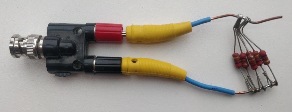
My multimeter reports this dummy load to come out at 44.8 Ω, so the SWR should be 50/44.8 or about 1.1. When measured in the 160 m band, the IC-705 display reports a perfect match at SWR 1.
For the record, here are some values for various frequencies as
obtained from the rig, using that mediocre dummy load. The readings
were obtained by sending l SWR as a network
command
to hamlib’s rigctld when connected to the transmitting rig. I
initially using nc from the Debian package netcat-openbsd, later a
few lines of python. This table is a bit
off-topic, as it informs you more about the (mediocre) quality of my
makeshift dummyload and the wonderful functionality of hamlib than
about the IC-705.
| QRG | SWR reported |
|---|---|
| 1850 | 1.05208 |
| 3650 | 1.01042 |
| 5360 | 1.02083 |
| 7100 | 1.04167 |
| 10125 | 1.10417 |
| 14175 | 1.19792 |
| 18100 | 1.29167 |
| 21225 | 1.375 |
| 24945 | 1.46875 |
| 28850 | 1.59375 |
These measurements were taken at 5 W power as demanded by the manual.
If low output power is used, all the way down to “0 %”, absolute SWR readings should be taken even less seriously. Nevertheless, they can still be used nicely to adjust an antenna tuner (at the desirably low interference to other traffic on the band a 50 mW signal affords).
I also like the ability to quickly gauge and graph SWRs over an entire ham band by pressing the PTT a few times. Here is a sample image of the bar graph that shows the inverted-U antenna as described below viewed through my Z-match antenna tuner:
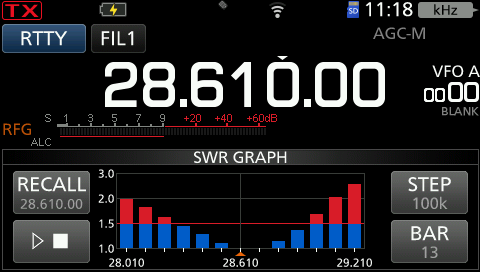
It is easy enough to pull this data via rigctld and a few lines of
python code, so for accessibility (and for good
Karma in general), here is roughly the same data with higher precision
as text. Why “roughly”? It had been a rainy day and it took me some
time to do the Python coding, so some change, probably in antenna
moisture, caused the point of best SWR to shift ever so slightly to a
higher frequency, without me touching the Z-match.
| QRG | SWR reported |
|---|---|
| 28010 | 1.98438 |
| 28110 | 1.85938 |
| 28210 | 1.6875 |
| 28310 | 1.47917 |
| 28410 | 1.32292 |
| 28510 | 1.14583 |
| 28610 | 1.0 |
| 28710 | 1.0 |
| 28810 | 1.11458 |
| 28910 | 1.34375 |
| 29010 | 1.64062 |
| 29110 | 1.98438 |
| 29210 | 2.55 |
Why QRP is fine with me (my antenna situation) 🔗
I live in a rented flat in a big city and cannot erect a permanent antenna. My shortwave transmissions use some sort of angle dipole, one wire roughly North into a friendly street tree, another along the house roughly West, both about 10 m above street level. For 40 m and higher, two wires as described, about 5-6 m length each, do. If I want to operate on 60 m and 80 m, I use longer wires. The additional lengths dangle down towards ground from the ends of the horizontal stretches in some sort of “inverted U” fashion. One dangling end is about 7 m, the other maybe 9 m long. In either case, the feedpoint is on my windowsill, and I have a 1:1 balun there. From there, a meter or two of 300 Ω twin-wire line to the tuner.
German rules allow either less than 10 W EIRP out of a radio amateur’s non-moving antenna, or that amateur has to do paperwork. The paperwork needs to demonstrate field strengths caused by your antennas do not exceed permitted limits in places where other people may roam.
Now my case is a bit peculiar. There is this wire “along the house”, and I have downstairs neighbors. Also, when I don’t operate (e.g., when there is the slightest risk of thunderstorms), the wire is pulled back into the house. I bring it back out the next time I plan to operate. Then the wire does not necessarily ends up at exactly the same place as before. Given all of these peculiarities, I consider that paperwork pretty hopeless. So I stay below 10 W EIRP.
To make matters worse: If I understood the legal situation right, when I don’t do the paperwork, I can experiment with antennas at will, as long as I stay below 10 W EIRP. Once I have done paperwork on any antenna present, I cannot simply erect a new antenna and decide to either use that new antenna below 10 W EIRP or the old one as documented. Instead, I would have to do new paperwork for each experimental antenna change before trying it out.
The touch screen + menu structure 🔗
Generally speaking: The more knobs and the fewer touch screen functionality, the better from an accessibility point of view. Now my eyes function well enough provided I’m wearing glasses, so I can live with a touch screen.
When operating outdoors, the screen visibility is not great. But by providing a bit of shade, I’ve always been able to read it, even in sunlight.
Overall, I find the menu structure of the rig comprehensible. I generally know where to find what, without needing to refer to the manual. It’s not easy to come up with such a menu system. Well done, ICOM!
What’s good could be even better. There are some improvements I would love to see, I would suggest as feature requests if the firmware were an open source project:
One sorry exception to “I know where to find stuff” is the CW keyer side tone audio level. I keep needing to check the manual where to find that. If given a choice, I would much prefer to have the side tone frequency buried in the depths of the menu and the side tone audio level be as readily accessible as the frequency now is.
Also, I don’t like “%” as a measurement unit for TX power. By the way, 0 % stands for an output somewhere in the 50 mW range; see my post on IC-705 power measurement.
And I like “%” even less as a measurement unit of the “REF adjust” frequency generation master clock adjustment. Also, I would like the manual to provide some crude answer to the obvious question: How much does one “%” of that adjustment change the final rig frequency? As it is, the manual actually does not even mention what this setting is or does. And the name “REF adjust” is a bit cryptic to begin with: What “REF”? I think “freq adj” would have been a better name. (Incidentally, they call two different things “REF adjust”. The other pertains to the spectrum waterfall.)
Yet, this setting is crucial for frequency calibration. With its help and a bit of patience, the IC-705 can be calibrated to below 1 Hz precision over the entire short wave range.
So, for your convenience, here is that data I would have liked the manual to mention: According to my own measurements, a decrease of 1 of this “%” number will increase the slope as shown by the WSJT-X frequency calibration by about 0.081 ppm. To nail the sign: A higher value of this “REF adjust” causes the actual dial frequency to move to higher frequencies, so any audio you’ll hear in USB mode will be slighly lower.
Weight 🔗
Complete with battery and microphone, my IC-705 weighs 1285 g. This is bearable. For comparison: The 10 m telescope antenna rod I usually haul up to my activations’ hilltops weighs some 2.5 kg. On the other hand, if every 100 g matters to you, lighter, more specialized (and more spartan) rigs can be had.
The microphone 🔗
I had the kitchen scale visit my radio shack for the previous paragraph. So it occurred to me to also measure the force required to push the microphone’s PTT. The scale showed about 420 g. After lengthy contributions to our weekly FM group, my fingers have consistently informed me: This is quite a lot.
USB 🔗
For a previous rig, I had crafted a setup with home-grown VOX PTT and audio cable. When on the market shopping for a new rig a good five years ago, I wanted to improve on that: “Just one USB cable and that’s it!” At the time, the IC-705 was one of very few rigs fitting that desire.
Since I had got it going, this “one USB cable” thing has been quite as convenient as I had hoped it would be.
But to actually get it going had been a bit more demanding than I would have hoped. Inside the rig, from a radio frequency point of view, the USB port does not seem to be isolated from the rest of the circuity. So if there is radio frequency energy on the rig, there will be radio frequency energy on the cable as well.
I have seen outright PC crashes. Winding the USB cable between rig and PC through a ferrite toroid some 10 times helped. But the USB was still quite unstable and in particular, the mouse pointer behaved bizarre (I use a USB cable mouse). Another toroid for the mouse cable helped somewhat, but it remained difficult to use the mouse during transmit. What finally helped was to keep radio frequency energy away from the rig’s ground level, by (in addition to the measures already mentioned) stringing the coax between tuner and rig five times though yet another ferrite toroid.
Arguably, ICOM could have provided better isolation inside of the rig, instead of letting the user do it outside.
Another USB deficiency in the rig’s USB: The socket is still µUSB.
When the rig came out, USB-C had been state of the art for quite some years. Yet ICOM chose to use the outdated µUSB.
They also didn’t employ “power over USB” seriously. Yes, you can charge the battery via USB. But you cannot push juice into the rig via USB that suffices for full-power TX.
WiFi 🔗
The rig’s offers WiFi connectivity. That initially looks like a way to dodge the “HF energy problem on the USB cable” problem. Unfortunately, ICOM chose to equip the rig with antiquated technology in this area, too: The WiFi operates on 2.4 GHz only. When the IC-705 came out, 5 GHz had already been state of the art for several years.
Why would that matter? I happen to live in a rented flat, third floor, in a big city. In this neighborhood, 2.4 GHz is drowned by all kinds of traffic. Attempts to stream real-time data via WiFi work only intermittently.
At least that was my result when I used the open source IC-705 WiFi access software kappanhang back in 2020. After an initial stuttering experience, and after I got USB working nicely for me, I did not try again.
Unfortunately, ICOM’s software to control the IC-705 via WiFi is closed source proprietary, and not intended to run under Linux. That bothers me, as I’m running a Linux-only shack. (I proudly boast that I never ran any MS (or Apple, for that matter) OS on the hardware privately used by me, since I directly went from (non-MS) DOS to Linux in the early 1990s and never looked back.) To make matters even worse, the protocol used between the rig and that software is not documented by ICOM and the developers of kappanhang had to reverse engineer it painfully.
Their assessment of the IC-705’s WiFi is telling (their emphasis):
Note that the built-in Wi-Fi in the Icom IC-705 has very limited range, and [sic] sensitive to interference. If you see a lot of retransmits in the log, or packet loss, then:
- Place the IC-705 close to your Wi-Fi AP/router, or use a Wi-Fi range extender device
- Make sure the Wi-Fi bandwith is set to max. 20Mhz in the Wi-Fi router (see explanation here)
- Try switching Wi-Fi channel on your Wi-Fi router. Only channels 1, 6 or 11 should be used (see explanation here)
Sometimes rebooting the transceiver helps, as the network stack in the IC-705 is not quite free of bugs. :)
I still use the WiFi stack of my IC-705. For I prefer clocks to be precise. The IC-705 nicely keeps time by setting its clock using NTP via WiFi. I like that.
GPS 🔗
In principle, the included GPS receiver could also set the device’s clock. I’ve seen the GPS work outside, but it is fairly deaf. My shack is in a steel-reinforced concrete building under a sheet metal roof. I cannot recall having seen the IC-705’s GPS get a fix there, ever, in all those years. For comparison: My smartphone, when firing up its GPS afresh, acquires a fix within half a minute or so, when sitting on my desk next to the rig.
For the record: My smartphone is fairly old, the model hit the market in 2017. I believe the IC-705 became available in 2020. That smartphone not only has better GPS, but also USB-C and 5 GHz WiFi.
Power supply 🔗
Under “power supply requirement”, the manual demands 13.8 V ±15 %, so that’s 11.73 - 15.87 V.
This lower bound is puzzling. After all, the rig can be powered by a ICOM-supplied battery that delivers only 7.4 V. (Even though at only 5 W maximal transmit power at that low voltage. Fair enough.)
I’ve been using various rechargeable batteries to power my IC-705, in particular sturdy 12 V LiFePO₄ with build-in care-free battery management system. Those batteries switch themselves off when output voltage has gone down to 8 V. That’s considerably below the 11.73 V demanded by the manual. I have not found adverse effects.
Those external batteries provide a nominal 6 Ah. They have been good for 10 hours of continuous CW contest search & pounce operation with 5 W output power. So during such operation, the rig’s average power consumption seems to be 600 mA.
Battery 🔗
The rig came with a clip on / clip off “BP-272” rechargeable battery pack with nominally 1.88 Ah capacity at nominally 7.4 V.
I find rather puzzling this stipulation from the manual:
Keep the battery pack attached, even when using an external power source.
The manual does not tell you why.
I asked the ICOM people at HAM RADIO fair in Friedrichshafen about this. I asked them a few times, in different years. But they were always quite as puzzled as I am.
For the record: The rig seems to run fine from external power even without a battery pack.
I like to have that clip-on rechargeable battery as a back-up. So when my exterior rechargeable is empty, the rig will not switch off in the middle of a QSO.
But that is exactly what it does, even if only briefly. It happened occasionally that my external LiFePO₄ was depleted and the rig switched to internal power in the middle of me talking on FM. Friends who were listening consistently reported a short interruption, a gap in my transmission, when that switch happened.
Overheating 🔗
In normal operation, it is not easy to overheat the IC-705. But it can be done. One way is talk for several minutes on FM, in particular when doing so with full power of 10 W.
You can watch the rig heat up, as ICOM devoted the lower right corner of the display to a thermometer display. When things get too hot, the rig reduces power.
During a solar eclipse, I tried to send WSPR signals on shortwave continuously for extended periods of time (hours). Continuous WSPR results in a duty cycle of 92 %. I had to reduce power to something like 500 mW to prevent overheating.
And I had to remove the battery pack.
For the place where the rig gets hot is the metal on which the battery pack sits when it is attached to the rig. So, when the rig becomes hot, you want to expose that to ambient air.
As long as the battery pack is attached (as the manual stipulates even when using external power), any excess heat goes right into the rechargeable battery, of all places!
This may be beneficial when operating the IC-705 outdoors in icy weather. But by and large, I find that a dubious engineering decision. In rechargeable battery circles, heat is considered unhealthy.
In an experiment done in the process of writing this, I did another long-term WSPR transmission with 100 % transmit periods. This was on 10 m. For an output of 5 W, I set TX power set to 59 %. The input audio from WSJT-X was such that the ALC just engaged with one bar.
The environment temperature in my shack was at 20° C, without draft or other perceptible air circulation. The rig sat normally on the desk, screen vertical, nothing touching else or leaning on it, so only the desk on which it sat hindered air circulation. The battery pack was removed. Tuner SWR was shown by the rig to be roughly 1.1 or 1.2. The drain current displayed by the rig was about 1.5-1.6 A. (There may have been a change during the heat-up, I did not watch drain current closely.)
I started to transmit 22:54 UTC on December 20, 2025. I probed heat using a no-touch infrared remote thermometer. The hottest place was at the central upper rim of the piece of sheet metal normally covered by the battery pack, just below the middle of the upper plastic bar. At about 45°C there, the first not-entirely-blue bar appeared on the thermometer display. This happened at 23:03 UTC, so about 7 minutes into the experiment. As mentioned, full-time WSPR comes out to 92 % duty cycle. At 23:16 UTC, so 22 minutes into the experiment, the hottest place reached a temperature of 56.6°C, the thermometer display reached the “hot” part and the transmit power was reduced to about half its previous value. At that time, the middle (center) of the sheet metal was 50°C hot, the lower parts 33-34°C.
According to the manual, the battery pack has an upper limit of 60°C. So the transceiver apparently does protect it from overheating even under such extreme circumstances as I subjected it to.
As a wild speculation: Maybe ICOM does not want us to be able to touch this part of the case when it’s at 56°C, to avoid being sued? And therefore asks us to keep the battery pack attached whenever the transmitter is operated - as thermal protection for probing fingers?
Firmware 🔗
One of the most unpleasant aspects of this mostly nice amateur radio rig: Its firmware is totally closed. There is not documented or known way to program it yourself.
We have to live with what ICOM gives us.
Incidentally: ICOM will allow you to install a new firmware only after you agree to something along the line: “If this firmware breaks my rig, I will not hold ICOM accountable.”
SD-Card 🔗
One can put an SD card into the rig. This allows the rig to write all kinds of information to that card. When seeing this for the first time, I thought this a mostly useless gimmick. I had a lesson to learn. By now, I’ve rather come to like it.
There is this CSV text file the rig writes that tells me when did I receive and when did I send on which frequency using which mode. In the receive case, it has the S-value of incoming signals, in the send case, which power was used. This can be immensely useful to correct goofs in log writing.
There is also an option to have the rig record the audio of signals sent or received. This nicely provides recordings of our weekly 2 m FM chats, to those that couldn’t make it that particular evening. As the audio recording happens with lowly 8 kHz 16 bit sampling rate in mono, the space of a typical SD card last a looong time. I’ve also used the audio recordings when taking part in the FMT in autumn 2025. But that’s another own story, to be told in a post of its own when/if I get around to doing so.
The SD card is also useful for other purposes: Backup of settings before doing experiments with them, screenshots of situations one wants to remember, firmware upgrade.
What I really do not like about the SD card: To access the treasures it holds, I have to physically fumble it out of the rig and insert it into my computer.
Hey, ICOM! There is a USB connection between the two. Smartphones with a price tag of a tenth or a twentieth of the IC-705 have no problems exposing contents via USB. Why can’t the IC-705 do that as well? At least read-only, if you can’t manage read-write?
I raised this issue with ICOM staff at the HAM RADIO fare in Friedrichshafen several years ago. They diligently took notes. As far as I can see in new firmware that came out recently, nothing noteworthy happened.
Unfortunately, the firmware is nailed shut. So there is no way for us radio amateurs to help ourselves. One just has to live with whatever ICOM gives us.
Spectrum waterfall 🔗
I use the waterfall a lot. Even during our local radio club’s weekly 2 m FM get-together, it is fun to watch how stations briefly crawl up or down to their final frequency, or how the club president’s signal is again too narrow, as usual.
During S&P work in a contest, when done with the present station, it is useful to already see the next station’s frequency, and to be able to navigate to that frequency within seconds, via two touches of the touch screen. When on CW, and using a touch-screen pen instead of my fingers, I’m typically within 10 or 20 Hz. The rig’s autotune happily does the rest. (I’m the kind of person who takes pride in operating transceive.)
Finally, the waterfall is quite helpful when hunting local noise and disturbances. One glance retrieves a lot of valuable information: Frequencies affected and periodicity (e.g., all 50 Hz, or all so-many-kHz, or whatever).
Stuff I have not or almost not used 🔗
-
The digital voice mode. It is not very enticing to me, as it is proprietary and requires central registration.
-
Build-in RTTY mode. I rarely dabble with RTTY, and when I do, prefer using
fldigion my PC for that. - That said, I do use RTTY mode regularly to produce an unmodulated carrier for antenna tuning, as suggested by the manual. -
The build-in CW Keyer macros. While those might be useful during my typical GMA activation, it has never occurred to me to actually use them.
-
I own a small Bluetooth boombox that I have used very occasionally to forward the rig’s audio to the next room. That works. But when I re-approach the rig carrying the boombox, I find the delay difference between the two audios causes a rather unpleasant echo experience. Now I’m not much a Bluetooth user to begin with, and the IC-705 has not changed that.
If you want to discuss this and have a Fediverse account, leave your comments below https://mastodon.radio/@dj3ei/115764513617938900.