The feedline antenna
Summary 🔗
- A simple antenna that is built from a length of 300 Ω twin-wire feedline, and some short piece of plastics.
- Budget antenna! The coax feedline you’ll attach to it will most likely be more expensive than the antenna itself.
- Mostly meant for 2 m, but can be used for 70 cm as well.
- Very light, so you can get it up high into the air on a flimsy telescope mast.
- But it has a few peculiarities you should be aware of.
What kind of an antenna is this? 🔗
This is a variant of the J-pole antenna.
Simultaneously, it is also a end-fed half wave dipole, fed via a quarter-wave stub. The upper 97.5 cm of the antenna form that dipole, the rest is the quarter-wave stub that feeds it.
As far as radiation and gain are concerned, this antenna performs like any (vertical) half-wave dipole does.
Material 🔗
The following instructions are for 300 Ω feedline with a velocity factor of 0.8. This is the line that has no windows.
The tough part is to obtain such 300 Ω feedline these days. Honestly, I do not know a source right now.
I myself bought mine from DX-wire when it was carried there, maybe some 12 years ago. Despite the cheesy name, DX-wire is a good, honest shop, the owner Peter is quite helpful, and I recommend that shop and especially their rods. I’ve been a happy customer of DX-wire’s products for at least 15 years, but am not affiliated or otherwise connected with it.
Another source with a good reputation I’m not hesitant to recommend is Kabel Kusch. They presently have windowed 300 Ω feedline that I expect to be quite usable for this kind of antenna. But as windowed line has a different velocity factor, the sizes given here will not work for that feedline; you will need a longer stub. Some remarks below may help you to get started.
Building instructions 🔗
The basic building instructions in German are contained in this sketch. The same information, with some more detail, follows as English text.
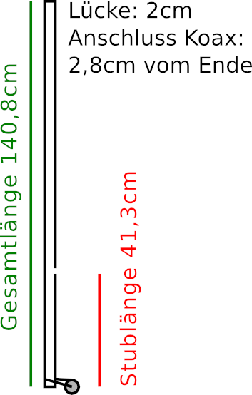
You start with a piece of feedline that’s about 142 cm long or longer.
Call one end the lower and the other the higher end.
Start with short-circuiting the lower end.
Next, 2.8 cm from the lower end, you attach a coax to the feedline. The coax screen is soldered to one conductor of the feedline, the inner conductor to the other. You’ll have to expose the conductors over a length of a mm or two, without cutting them. A sharp knife, a cutting board, and a bit of patience generally do the trick.
The sketch is a bit symbolic here. The lengths of the two coax conductors to their respective solder joints should be as short as you can make them. The length of the coax should extend downwards, in line with the feedline.
If you goof on the first try, but you have enough feedline left, you can cut off the bottom 3 cm or so and start over. Short circuit the lower end, measure 2.8 cm, attach the coax.
Bend the 2.8 cm feedline length so it sticks a bit away from the coax. A 30° or 45° angle or so is enough.
Next, you need to cut your feedline to length. You need to end up with a total length, from one end to the other, of 140.8 cm. But the upper end needs to be short-circuited as well! So cut a little longer, adding the width of the feedline to the 140.8 cm. Then remove the inner material and strip the two conductors over such a length that the stripped conductors start 140.8 cm from the short circuit on the other end.
Short circuit the upper end.
Finally, a total of 41.3 cm from the lower end, you cut one of the two conductors of the feedline. It does matter which one: You need to cut the one that is soldered to the coax screen.
Another 2 cm above that cut, you need to cut that same feedline conductor again. Then remove those 2 cm of that conductor.
Done. The electric part of the antenna is completed.
If all is well, the feedline will show SWR better than 1.4 over the entire 144-146 MHz range, if mounted correctly. Mounting is somewhat critical, see below. For tuning hints, see below, too.
There is some suspicion that the lengths as given here are maybe a bit long. If you dare to, you can try a stub length of 41.0 cm and a total length of 140.0 cm.
This antenna can also be used on 70 cm.
Mechanical support for the solder joints 🔗
The solder joints between the coax and the feedline will break eventually if subjected to even moderate mechanical stress.
Attach some reasonably stiff stick of plastic to the coax below and also to the feedline above the solder joints. Fortunately, this is not a fiddly spot, so you can pretty much use what you have. A literal stick of wood would probably work, too.
The idea is: If you pull at the feedline and the coax, none of that force reaches the solder joints.
For the attachment of the stick to the antenna, I personally used stone age technology: Rope wrapped around both. That is, a piece of thin plastic rope tied some ten times quite firmly around both coax and my plastic stick (I used a piece of thin plastic tube maybe 10 or 15 cm long), and another such around the feedline and my plastic stick. Cable ties would also work.
Mounting is a bit fiddly. 🔗
This feedline antenna is an end-fed half-wave antenna. Like many such antennas, it is somewhat fiddly, does not like stuff near the dipole ends.
Where are the dipole ends? That is, where are the fiddly spots? The upper end of the antenna is one, and the general vicinity of the gap, that is, the place where one of the conductors is cut, the other.
Do not use adhesive tape or heat-shrink tube over the 2 cm gap to waterproof it. It will cause the frequency of the antenna to drop considerably.
Also, try to keep some distance of 5, better 10 cm between those two fiddly spots and whatever rod you use to lift it up. The rod should be fiberglass, or some other plastics. Do not use carbon fiber!
Personally, I stick my rod out of the window. Therefore it does not go straight up, but at an angle. But I want the antenna straight vertical. So I tie it to the rod tip with a piece of rubber string and let it dangle a bit.
A remark on those rubber strings: I cut them from used bicycle inner tube, which I get from my local bike shop for the asking. The strips are about 20-30 cm long, 1 cm wide. I use these rubber strings a lot to attach stuff.
But I do not tie the very upper end of the antenna. I let that stick up 10 cm above the rod’s end, so tie the antenna 10 cm down to the tip of the rod. After all, the antenna’s tip is one of the two fiddly spots, so I want to keep that out of harm’s way! (If that 10 cm bend a bit, I’ll rotate the rod so the bending points mostly upwards. But that probably doesn’t matter much.)
Suspended this way, the antenna dangles down. That is just as well, as it keeps the second fiddly spot (where the 2 cm gap is) away from the rod. I measure out a length of coax and tie that to the rod with another rubber, about as high as the lower end of the antenna dangles. This way, the coax forms a little horizontal bow from the lower antenna end to the rod. There’s slack, the antenna itself can still dangle freely.
I then lead the coax down the rod. I fix it to the rod with yet another of my rubber strings every 2 m or so.
That’s what I do out of my fourth-floor window.
If I’m elsewhere, I may need to attach this antenna to a rod that’s vertical. I’ll again let it stick out over the top of the rod by some 10 cm, tie it to the top there, and then tie it a little above the coax so that it bulges slightly. A distance of some 5 cm, better 10 cm between mast and the fiddly gap spot is healthy. If I need to, I can tie the antenna with another rubber strip some 40-50 cm from its top end. That comes out as the middle of the dipole; the antenna is quite non-fiddly there.
Tuning 🔗
If your antenna’s best SWR is at a frequency much lower than the band center at 145.000, you can try to tune it.
We tried that yesterday, when an antenna built for a friend to the above specifications was maybe a MHz low in frequency.
We have found out the hard way that simply removing some length from the upper end has less than the desired effect.
Naively, one would think: This is a half-wave dipole at 145 MHz, so removing 0.67 mm should lift the frequency up by 100 kHz.
But in practice, removing that length actually seems to do only roughly half of the expected lifting in frequency.
But after a lengthy process of several rounds of trial and error, we still finally got the frequency good enough yesterday.
Only afterwards, it dawned on me: For each mm that we shortened the antenna at the upper end, we should have also cut half a mm from the stub wire that is connected to the coax shield, making the gap slightly longer than its initial 2 cm. We didn’t actually try that. But you may.
Waterproving 🔗
Adhesive tape is fine over the joins to the coax, but do not use it over the gap and preferably not over the upper end of the antenna.
Still, it is a worthy goal to seal up everything so water will not creep into the wires or the coax. I personally smeared some glue over the wires. Not sure how well that actually worked, but maybe it did.
But even if the goal is achieved, the antenna still prefers to be operated in dry weather. If you have appreciable moisture build-up in the region of the gap, SWR will suffer.
I do not use my antenna in a permanent setting, but stick the rod out of the window when I want to operate and pull it back in afterwards. Not being able to shut the window poses somewhat of a challenge in both stifling climate catastrophe-induced summer heat and winter snow drizzle, but it is fine during the more moderate seasons on dry days.
That said, the antenna has been giving me a lot of faithful service. I have been using it in our weekly local FM round for at least 11½ years.
Maybe other feedlines? 🔗
You should be able to build the antenna with 300 Ω window line, or even with the also windowed more popular 450 Ω feedline, but then you’d have to experiment with the sizes. See to it you get feedline that is constructed from stranded wire as the two conductors. Some cheap offers give you solid wire; I’d be afraid that such wire will eventually break.
If I wanted to do that, I’d start with determining the length of a quarter wave stub at 145 MHz. For that, I’d attach a resistor of 1.8 kΩ at the other end of 300 Ω line, or 4.05 kΩ at the other end of 450 Ω line. These are the values a quarter-wave stub of that feedline will transform to 50 Ω.
So I’d try to find the length where SWR is minimal at 145 MHz. That only needs a trx that can measure SWR at low power, and resistors that can take that low power for a few seconds at a time. If you have sophisticated measurement instruments, you’ll probably find an (even) easier way.
That would be what I’d use in place of the 41.3 cm. The remaining 97.5 cm above the gap I would leave alone initially, regardless of feed line used.
Discussion opportunity 🔗
If you want to comment or discuss this piece and have a Fediverse account, feel invited to answer my pertinent toot.